Appearance
Three.js 内置了很多几何体模型供我们使用,但其实我们完全可以自定义任何形状的几何体。
任何几何体都是从点->线->面组成,因此,我们只需要知道如何绘制点、线、面,然后就可以绘制任何形状了。所以先从点,线,面的绘制开始介绍。
绘制“点”
Three.js 中并没有提供直接绘制“点”的几何模型,但是我们可以通过 BufferGeometry来实现。BufferGeometry是 threejs 内置的一个核心类,所有内置的几何体都是基于它创建的。任何绘制的屏幕的画面,都是基于顶点开始的,而 BufferGeometry就是通过缓冲区来存储顶点数据的。
只要有了“点”,就可以组成线,面,自定义几何体了。创建“点“的方法如下:
js
// 创建缓冲几何体
const geometry = new THREE.BufferGeometry()

// 使用 Float32Array 存储顶点数据, 顶点数据 3 个一组表示三维坐标
// 这是只创建三个点,一共 9 个顶点数据
const vertices = new Float32Array([
  0, 0, 0,
  100, 0, 0,
  0, 100, 0
])
// 给缓冲几何体设置顶点位置,参数 3 表示每个顶点都是一个三元组组成
geometry.setAttribute('position', new THREE.BufferAttribute(vertices, 3))

// 创建点材质,size设置点大小,color设置点颜色
const pointMaterial = new THREE.PointsMaterial({
  size: 10,
  color: 0xff0000
})

// 创建点对象
const points = new THREE.Points(geometry, pointMaterial)

// 加入场景中显示
scene.add(points)
代码中省略了一些必要的创建步骤,如创建场景、相机、渲染器等,只看关键的“点”绘制部分。最终效果如下:
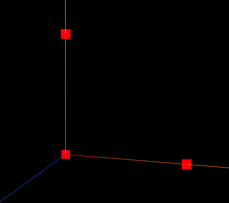
可以看到三个点都被正确绘制了。只是这里点的颜色都是统一设置了,我们可以为每一个点单独设置颜色,其实顶点数据也可以设置颜色,操作如下:
js
const geometry = new THREE.BufferGeometry()

const vertices = new Float32Array([
  0, 0, 0,
  100, 0, 0,
  0, 100, 0
])

// 创建颜色数组,长度需要与顶点位置一一对应
const colors = new Float32Array([
  1, 0, 0, // 第一个点红色
  0, 1, 0, // 第二个点绿色
  0, 0, 1 // 第三个点蓝色
])

// 设置顶点颜色,同位置设置
geometry.setAttribute('color', new THREE.BufferAttribute(colors, 3))

geometry.setAttribute('position', new THREE.BufferAttribute(vertices, 3))
const pointMaterial = new THREE.PointsMaterial({
  size: 10,
  // color: 0xff0000
  vertexColors: true // 启用顶点颜色渲染
})
const points = new THREE.Points(geometry, pointMaterial)

scene.add(points)
效果如下: 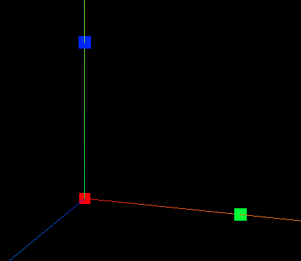
颜色取值范围 0~1,表示 RGB 的分量,更多的颜色可以多多尝试。
绘制“线”
了解了“点”的绘制,绘制“线”就简单了,只要点的数量大于1,然后把点与点之间连接起来,就有了“线”。我们直接拿上面绘制“点”的代码来修改,将”点“用线连接起来。如下:
js
const geometry = new THREE.BufferGeometry()

const vertices = new Float32Array([
  0, 0, 0,
  100, 0, 0,
  0, 100, 0
])

// 创建颜色数组,长度需要与顶点位置一一对应
const colors = new Float32Array([
  1, 0, 0, // 第一个点红色
  0, 1, 0, // 第二个点绿色
  0, 0, 1 // 第三个点蓝色
])

// 设置顶点颜色
geometry.setAttribute('color', new THREE.BufferAttribute(colors, 3))

// 设置顶点位置
geometry.setAttribute('position', new THREE.BufferAttribute(vertices, 3))

// 创建线材质
const lineMaterial = new THREE.LineBasicMaterial({
  vertexColors: true // 启用顶点颜色渲染
})
// 创建线
const line = new THREE.Line(geometry, lineMaterial)
// 加入场景
scene.add(line)

// const pointMaterial = new THREE.PointsMaterial({
//   size: 10,
//   vertexColors: true // 启用顶点颜色渲染
// })
// const points = new THREE.Points(geometry, pointMaterial)
// scene.add(points)
绘制“线”和“点”一样,只是把材质(替换成 LineBasicMaterial)和形状对象(用 THREE.Line)换了就行。把坐标系辅助去掉,看效果如下:
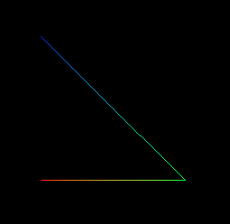
因为三个顶点设置了颜色,并且启用vertexColors: true,所以顶点之间的线条是渐变的颜色。另外使用 THREE.Line 不会将首位顶点相连,可以使用 THREE.LineLoop 来绘制首位相连的线:
js
const line = new THREE.LineLoop(geometry, lineMaterial)效果:
此时线就是闭合的。然后你会想到所有的线都在同一个平面上,这是不是就绘制出了一个“面”?答案是否定的。
绘制“面”
首先要明确的是,在同一个平面上的顶点,用线围起来的闭合图形,不是一个“面”,它只是一个线框结构。
threejs中一个最简单的“面”是三角形,可以说所有的几何体都是由一个个三角形组成的。比如一个平面矩形几何体就是两个三角形组成的,官方演示:平面缓冲几何体(PlaneGeometry)。
现在我们来自定义一个最简单的三角形:
js
const geometry = new THREE.BufferGeometry()

const vertices = new Float32Array([
  0, 0, 0,
  100, 0, 0,
  0, 100, 0
])

geometry.setAttribute('position', new THREE.BufferAttribute(vertices, 3))

// 使用  MeshBasicMaterial 材质
const material = new THREE.MeshBasicMaterial({ color: 0x00ff00 })

const triangle = new THREE.Mesh(geometry, material)

scene.add(triangle)
绘制结果如下:
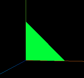
顶点的创建跟之前绘制“点”,“线”一致,只不过这里绘制“面”需要用到 MeshBasicMaterial 材质,可以发现对于“面”的颜色设置,会让整个平面都变成对应的颜色,而不仅仅是线条或者点。除了颜色之外还可以设置很多属性,这里不展开,查看官方文档 MeshBasicMaterial。
这里有一个需要注意的地方,就是顶点的设置顺序需要逆时针,threejs中规定从相机角度看,逆时针创建为正面,顺时针创建为反面。如上面例子中的顶点[0, 0, 0, 100, 0, 0, 0, 100, 0]就是逆时针的,所以可以从屏幕上看到这个三角形,如果设置为 [0, 0, 0, 0, 100, 0, 100, 0, 0]就是顺时针了,默认是看不到的。如果需要正反面都可以显示在屏幕,可以在材质中设置 side: THREE.DoubleSide。
绘制出三角形就几乎可以绘制出任何形状的几何体了。这里会以矩形为例,因为涉及一个重复顶点的问题。绘制一个矩形需要几个顶点,答案是 6 个,可千万别觉得是 4 个,时刻记着矩形也是三角形拼接的,两个三角形可以拼接成一个矩形。代码:
js
const geometry = new THREE.BufferGeometry()
const vertices = new Float32Array([
// 第一个三角形顶点
0, 0, 0,
100, 0, 0,
0, 100, 0,
// 第二个三角形顶点
0, 100, 0,
100, 0, 0,
100, 100, 0
])
geometry.setAttribute('position', new THREE.BufferAttribute(vertices, 3))
const material = new THREE.MeshBasicMaterial({ color: 0x00ff00 })
const plane = new THREE.Mesh(geometry, material)
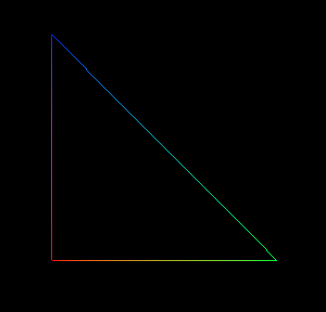
scene.add(plane)效果:
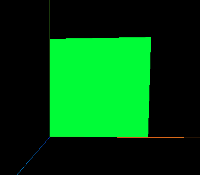
图中矩形平面是两个三角形拼接而成的,注意两个三角形都是顶点逆时针绘制的。可以将几何体渲染成线框查看,设置材质属性:
js
const material = new THREE.MeshBasicMaterial({
  color: 0x00ff00,
  wireframe: true // 渲染成线框
})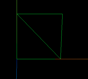
这就比较明显的看出两个三角形了。
解决顶点重复
上面绘制矩形平面的例子中,有 6 个顶点,其中有两个顶点是重复的,即 100, 0, 0 和 0, 100, 0 都各自出现了两遍。如果总的顶点数据很多,重复的多的话,看起来就很繁琐,这种情况可以给顶点加索引来解决。
做法就是给第一次出现的顶点设置新的索引,重复出现的就用相同索引代替,然后设置完整的索引顺序。修改矩形平面例子,代码:
js
const geometry = new THREE.BufferGeometry()

const vertices = new Float32Array([
  0, 0, 0, // 0
  100, 0, 0, // 1
  0, 100, 0,  // 2
  // 0, 100, 0,  // 2 // 重复的索引,不用再写
  // 100, 0, 0,  // 1 // 重复的索引,不用再写
  100, 100, 0 // 3
])

// 创建索引
const indexs = new Uint16Array([0, 1, 2, 2, 1, 3])
geometry.setIndex(new THREE.BufferAttribute(indexs, 1))

geometry.setAttribute('position', new THREE.BufferAttribute(vertices, 3))

const material = new THREE.MeshBasicMaterial({ color: 0x00ff00 })

const plane = new THREE.Mesh(geometry, material)

scene.add(plane)
重复的索引不需要再列举,只要建立对应的索引就行。效果是一样的,这里不再展示。
绘制几何体
Three.js 内置的几何体覆盖了大多数基础需求,但对于复杂形状,可以通过 BufferGeometry 和 BufferAttribute 自定义顶点数据来构建。其实建模的核心原理就是通过顶点定义三角形(或三角形面片),再将这些三角形组合成几何体。顶点数量越多,模型细节通常越丰富,但需注意性能优化。
一般复杂的几何体都需要借助软件来建模,再导入 Three.js 程序中,这里就不再展开。
为了练习上面所学,我们来自定义一个立方体。一个立方体是有 6 个面构成,每个矩形面至少有两个三角形。这里列举出所有顶点数据,不建立索引了,看的直观点。
js
const geometry = new THREE.BufferGeometry()

const vertices = new Float32Array([
  // 前面
  0, 0, 0,   100, 0, 0,   100, 100, 0,  // 三角形1
  0, 0, 0,   100, 100, 0,   0, 100, 0,   // 三角形2

  // 后面
  0, 0, -100,  100, 0, -100,  100, 100, -100,
  0, 0, -100,  100, 100, -100,  0, 100, -100,

  // 左面
  0, 0, 0,  0, 0, -100,  0, 100, -100,
  0, 0, 0,  0, 100, -100,  0, 100, 0,

  // 右面
  100, 0, 0,  100, 0, -100,  100, 100, -100,
  100, 0, 0,  100, 100, -100,  100, 100, 0,

  // 下面
  0, 0, 0,  100, 0, 0,  100, 0, -100,
  0, 0, 0,  100, 0, -100, 0, 0, -100,

  // 上面
  0, 100, 0,  100, 100, 0,  100, 100, -100,
  0, 100, 0,  100, 100, -100,  0, 100, -100
])

// 顶点颜色数据,对立面的颜色设置相同
const colors = new Float32Array([
  // 前面
  1, 0, 0,   1, 0, 0,   1, 0, 0,
  1, 0, 0,   1, 0, 0,   1, 0, 0,

  // 后面
  1, 0, 0,   1, 0, 0,   1, 0, 0,
  1, 0, 0,   1, 0, 0,   1, 0, 0,

  // 左面
  0, 1, 0,   0, 1, 0,   0, 1, 0,
  0, 1, 0,   0, 1, 0,   0, 1, 0,

  // 右面
  0, 1, 0,   0, 1, 0,   0, 1, 0,
  0, 1, 0,   0, 1, 0,   0, 1, 0,

  // 下面
  0, 0, 1,   0, 0, 1,   0, 0, 1,
  0, 0, 1,   0, 0, 1,   0, 0, 1,

  // 上面
  0, 0, 1,   0, 0, 1,   0, 0, 1,
  0, 0, 1,   0, 0, 1,   0, 0, 1,
])

geometry.setAttribute('color', new THREE.BufferAttribute(colors, 3))

geometry.setAttribute('position', new THREE.BufferAttribute(vertices, 3))

const material = new THREE.MeshBasicMaterial({ vertexColors:true,side:THREE.DoubleSide })

const plane = new THREE.Mesh(geometry, material)

scene.add(plane)
效果:
可以看到手动定义立方体的顶点数据(如逐行编写36个顶点坐标和12个三角形面片)不仅代码冗长且极易出错,这还只是基础模型。面对复杂场景(如人物、机械零件等)根本无法下手,所以实际开发中一般就下面三种方式建模:
- 内置几何体:直接使用 BoxGeometry、SphereGeometry 等标准化模型;
- 参数化生成:通过 LatheGeometry(旋转成型)、ExtrudeGeometry(路径挤出)等基于数学规律的生成器动态构建;
- 外部模型导入:通过 GLTFLoader 等工具导入 Blender、Maya 等专业工具制作的高精度模型,实现复杂结构与材质的完整迁移。
完毕。